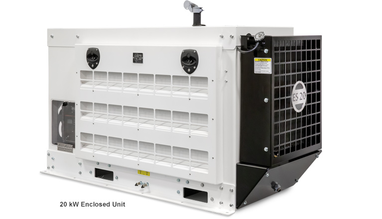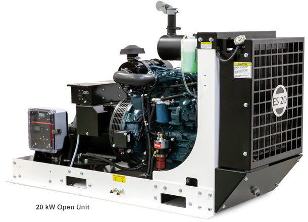
20 kW & 40 kW Emergency Stationary Generators
These generators are powered by an Emergency Stationary Reciprocating Internal Combustion Engine (RICE) as defined in 40 CFR § 63.6675 “to provide electrical power…during an emergency situation.” Therefore this generator may not be operated for maintenance and non-emergency situations in excess of the limits outlined in 40 CFR § 63.6640.
These EPA regulations require the unit be installed permanently in a stationary location and, therefore, this unit may not be used in mobile applications under penalty of law as outlined in 40 CFR § 1068.101 (b)(3). When installing this unit, the user should also ensure compliance with all state and local ordinances pertaining to this type of equipment.
Standard Features
- Compliant with EPA Emergency Stationary ICE Standards
- Powered by a Kubota engine
- Heavy duty design and construction for dependable performance and long product life
- Quiet and smooth running
- Easy installation hook-ups
- 2-wire start
- On-board battery and cables
- Battery charger
- 11-gauge steel construction
- 2-step powder-coated paint
- Non-corrosive aluminum doors
- Coolant heater
- Standard muffler
- Various options available

Contact us for details and pricing.
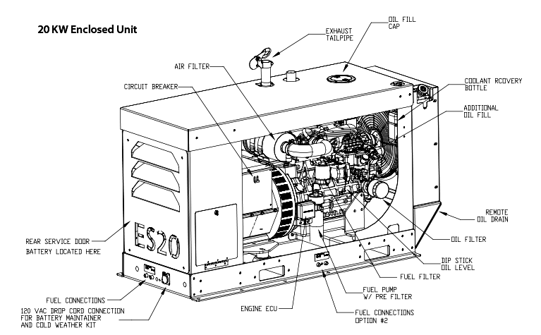
Typical Construction

EPS 20 kW & 40 kW Diesel Standby Generator Specifications
| Configuration | 20 kW | 40 kW |
|---|---|---|
| EPS Model Number | ES10020XXX | ES10040XXX |
| KW – Stand-by (1) | 20.0 | 40.0 |
| KW – Continuous (1) | 18.2 | 36.3 |
| 120 / 240V (Single Phase Continuous Amps) | 152 / 76 | 282 / 151 |
| Engine | Kubota V2203 BG | Kubota V3600-T-E3BG |
| Fuel Consumption (US Gal./hr.) @ 25% / 50% / 100% Load | .61 / .97 / 1.58 | .75 / 1.506 / 3.00 |
| Length (inches) | 57.52 | 72.00 |
| Width (inches) | 27.00 | 27.00 |
| Height (inches) | 37.39 | 41.39 |
| Weight (including oil & antifreeze) | 1,278 lbs. | 1,639 lbs. |
(1) All unit ratings are established at 1.0 power factor, 68 degrees F and 500 ft. above sea level. De-rate unit by 3.5% for every 1000 ft. above 500 ft. and 1% for every 10 degrees F above 68 degrees F.
(2) Sound level tests were performed on a unit in an open environment, pusher-fan model with all 5 generator cooling vents open. A typical installation will result in lower sound levels.
Illustrations shown may include optional equipment. Specifications subject to change without notice.
Mounting Requirements
Concrete Pad
Most local regulations will require the generator be mounted to a suitable concrete pad. Mounting holes are provided throughout the length of the generator for this purpose. Additionally, the installer should consider mounting the unit at least 12” above grade to permit adequate access to the oil drain when service is required.
Consider the Cooling Air Flow
It is very important to choose a mounting location that will provide adequate cooling airflow into the generator, while also allowing the warm air to be discharged. This is the most important part of the installation from a performance and longevity standpoint. A minimum of 24 inches of space around the entire genset enclosure is recommended.

